 |
|
 |
|

|
TotalPurge is the AutoCAD app for complex drawing optimization |
|
|
|
|
|
|
|
|
|
|
TotalPurge settings
Selecting and configuring optimization types
|
Figure 1 shows the "Optimization" tab of the "Program settings" window. Here you can select the entity optimization method, configure block optimization parameters, and activate the block creator.
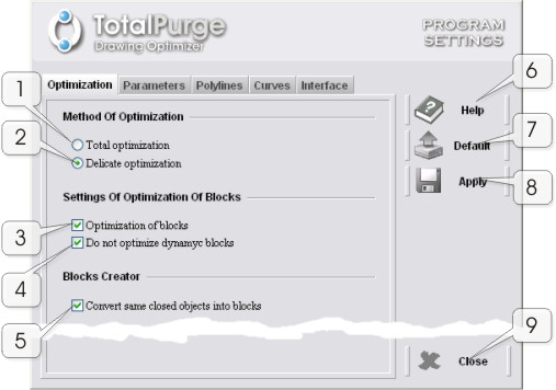 |
Fig. 1
"Optimization" tab |
Optimization method
- (1) "Total optimization" radio button
Allows the program to carry out optimization-conversion of selected entities within a single operating cycle. During the process, in place of source entities it creates objects with updated properties. Those properties include: linetype, color, lineweight, and linetype scale.
Entity properties are calculated using the average algorithm: from the number of selected objects, the program identifies the most frequently used properties. After that, those properties are set to new entities that have undergone the optimization process. With this optimization method, you can achieve the most thorough clearing of a drawing.
This method is recommended for cases when the drawing demonstrates a clear layer-by-layer arrangement: all objects located within a certain layer have identical (or close by value) properties.
- (2) "Delicate optimization" radio button
Allows the program to carry out preliminary grouping of objects with identical properties for further optimization-conversion. During the process, the program analyzes and takes into account – besides belonging to same layer – the following entity properties: linetype, color, lineweight, and linetype scale.
In other words, in this case optimization is carried out in portions; i.e., the process repeats in loop for each group of objects identical by properties. This optimization method is more appropriate in relation to the original drawing. However, in terms of clearing a drawing from redundant entities, it is somewhat less efficient than the total optimization method (that is especially noticeable with large numbers of entities having different properties). Nevertheless, in some tasks, where the goal is to maintain, for example, the original color of each object, you should rather use this method.
Delicate optimization is turned on by default.
Block creator
- (5) "Convert same closed objects into blocks" checkbox
Launches the "Block creator" tool. More on its operation is available in the respective section.
- (6) "Help" button
Opens context help
- (7) "Default" button
Resets all configuration settings to their default values.
- (8) "Apply" button
Saves all configuration settings made by user.
- (9) "Close" button
Closes the "Program settings" window.
Configuring optimization parameters
|
On the "Parameters" tab (Fig. 2), you can configure primary and secondary optimization parameters.
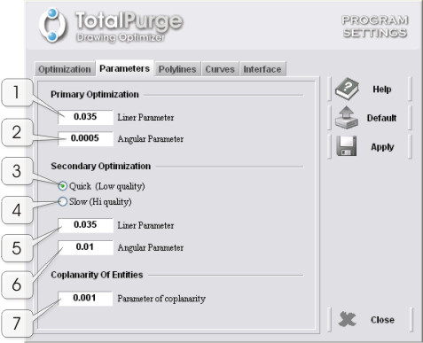 |
Fig. 2
"Parameters" tab |
Primary optimization
- (1) "Linear parameter" text box
Sets linear parameter for primary optimization. This parameter's value affects the degree of approximation in primary optimization of linear objects (LINE, CIRCLE).
- (2) "Angular parameter" text box
Sets value to the angular parameter for primary optimization. This value affects the degree of approximation in primary optimization of objects using angular values (ARC).
Secondary optimization
- (3) "Quick" radio button
Allows the application to run with minimum CPU consumption rate while performing secondary optimization. Optimization quality with this option enabled somewhat suffers.
- (4) "Slow" radio button
Configures the application's core to achieve the maximum degree of secondary optimization. When running in this mode, the program consumes more CPU power than it does in the "Quick" mode.
- (5) "Liner parameter" text box
Sets value to the linear parameter for secondary optimization. This value affects the degree of approximation in secondary optimization of linear objects (LINE, CIRCLE).
- (6) "Angular parameter" text box
Sets value to the angular parameter in secondary optimization.
Coplanarity of entities
- (7) "Parameter of coplanarity" text box
Sets uncoplanarity ratio for entities located in different user coordinate systems (UCS).
Note. The higher are the parameter values in primary and secondary optimization, the rougher is the approximation. And vice-versa – the smaller are the parameter values, the more precise is the approximation. However, setting too little values to these parameters is not recommended.
For engineering drawings, it is recommended to use the default values. For construction drawings (depending on scale and complexity of drawing) the values are to be increased. |
Configuring conversion of objects into polylines
|
Figure 3 shows the "Polylines" tab, where you can configure methods for converting basic objects into polylines:
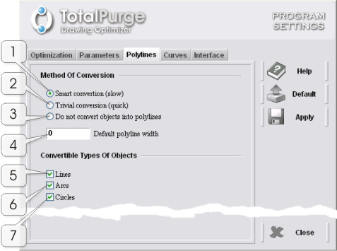 |
Fig. 3
"Polylines" tab |
Conversion method
- (1) "Smart conversion" radio button
Enables the so-called smart method for converting objects into polylines.
For more information on conversion methods, please see Converting objects (entities) into polylines.
- (2) "Trivial conversion" radio button
Enables the trivial method for converting objects into polylines.
For more information on conversion methods, please see Converting objects (entities) into polylines.
- (3) "Do not convert objects into polylines" radio button
Disables converting objects into polylines. In this mode, the program only performs entity optimization.
- (4) "Default polyline width" text box
In this field, you can set the default value to polyline width. The program uses this parameter when converting objects into polylines is enabled.
Convertible object types
- (5), (6), (7) "Lines", "Arcs", and "Circles" checkbox
By checking the respective check boxes, you can select the basic types of objects to be converted by the program into polylines (provided that converting entities into polylines is enabled).
These objects include the following basic entities: LINE, ARC, and CIRCLE.
Configuring settings for converting curves into polylines
|
Figure 4 shows the "Curves" tab, where you can make settings for converting curves into polylines:
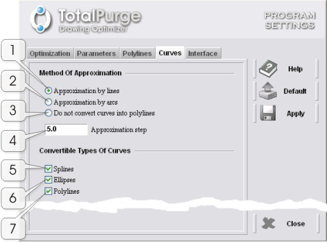 |
Fig. 4
"Curves" tab |
Approximation method
- (1) "Line approximation" radio button
Enables converting curves using the linear segment approximation method (enabled by default).
- (2) "Arc approximation" radio button
Enables converting curves using the arc segment approximation method. Compared to the linear segment approximation method, this method produces smoother polylines, which with certain settings are extremely close to the original object .
- (3) "Do not convert curves into polylines" radio button
Disables converting any curves into polylines.
- (4) "Approximation step" text box
Sets approximation step for converting curves into polylines. The higher is the value of this parameter, the rougher is approximation. The default value is 5.
Too little values in this parameter lead to a substantial increase of the number of vertices in polylines produced by the conversion of curves and, consequently, to the increase of the drawing file size. Therefore, it is recommended to choose approximation step with reference to of the drawing.
Convertible curve types
- (5), (6), (7) "Splines", "Ellipses", and "Polylines" checkbox
Here you can select the types of curves to be converted by the program into polylines (provided that converting entities into polylines is enabled; see "Configuring conversion of objects into polylines").
Curves include the following entities: SPLINE, ELLIPSE, and POLYLINE with the curve-fit or spline-fit properties.
For more information on converting curves into polylines, please see "Converting splines and other curves into polylines".
Some of the application's interface settings can be edited on the "Interface" tab (Fig. 5):
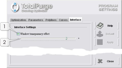 |
Fig. 5
"Interface" tab |
Interface settings
- (1) "Window transparency effect" checkbox
This button enables or disables window transparency. This effect applies to all of the application's windows. With this option enabled, when the mouse pointer appears outside the boundaries of any of the application's windows, the latter gradually becomes semi-transparent. And vice-versa, when the mouse pointer is within a window, it gradually restores its appearance.
- (2) Window transparency slider
Once all the settings are made, they are to be saved before continuing with the application. To do so, click the "Apply" button. Once everything is saved, you can leave the settings window ("Close" button).
Restoring default settings
|
To restore the initial system settings, click the "Default" button.
|
|
|
|
Copyright © 2022 DEBALANCE |
|
 |
|
 |
|
|