TotalPurge overview
This software is designed for a broad range of professionals using AutoCAD suite as their primary tool.
TotalPurge is a plugin – a high-performance application written in C++, which integrates into AutoCAD environment.
A convenient classical setup wizard facilitates the installation of the software to user's computer (please see Installing TotalPurge for more information).
TotalPurge was conceived as a universal solution for clearing drawings (not to be confused with the PURGE command) of redundant graphic objects (entities).
On this website, we are introducing a definition of optimization, which essentially means clearing. Optimization is carried out layer-by-layer; i.e., from a group of selected objects the program filters out objects of a certain type belonging to a specified layer, analyzes the position of those in the drawing and removes redundant entities that carry excess geometric constructions.
On the optimization step, the program can handle the following entity types: LINE, ARC, CIRCLE, and POLYLINE, as well as blocks, which may include objects of all the listed types.
|
|
Another functional feature of the software is the internal algorithm for converting objects into polylines. In other words, in place of an ordered group of objects the program can create multiple-vertex polylines.
In addition, the software implements converting into polylines curve entities, such as:
- splines
- ellipses
- polylines with spline-fit and curve-fit attributes derived from the AcDb2dPolyline class.
For more information on the essence of optimization, please read Definition of optimization and Illustrative example of optimization.
To start using TotalPurge:
- (1) Download the setup file suitable to your operating system's bit version (see "Download").
- (2) Install the software on your computer (see "Installation").
- (3) Run the AutoCAD the software was installed for.
- (4) Open a work drawing.
- (5) Run TotalPurge from the command line or using the respective button on the toolbar.
Launching the application
|
To launch the application, in the AutoCAD command line, type _TOTALPURGE or the respective short alias _TPURGE (see Fig. 1):
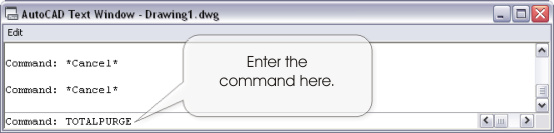 |
Fig. 1
To launch the application, type
TOTALPURGE or its short alias TPURGE |
You can also launch the application using the respective button on the toolbar (Fig. 2):
| Toolbar button |
Command |
Description |
 |
_TOTALPURGE
_TPURGE |
Launch application |
 |
_TPSETTINGS |
Program settings |
 |
_TPHELP |
Display help |
|
Fig. 2
Buttons and commands available
user after installing the software. |
The application's main window that appears when the program starts for the first time is shown on Fig. 3:
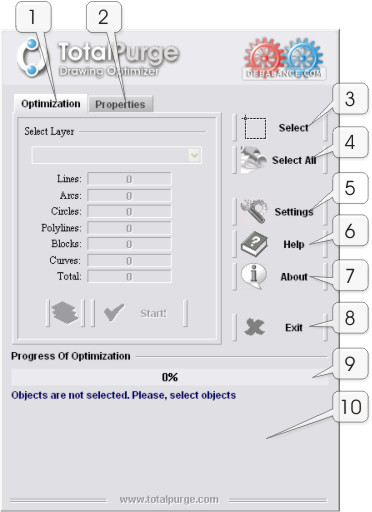 |
Fig. 3
Application's main window
after the first launch |
Controls in the main window
- (1) "Optimization" tab
Here you can find the main controls for managing the optimization process. This window comes up when the application starts and contains information on the selected layer and its objects.
To launch optimization (including conversion of objects to polylines), click the "Start!" button at the bottom of the window.
For more information, please see "Selecting layer" and "Launching optimization ".
- (2) "Properties" tab
In this window, you can set properties (line type, line weight, color, as well as polyline width in case the convert objects to polylines option is selected) for the new optimized objects created using the total optimization mode.
For more information, please see "Setting entity properties".
- (3) "Select" button
Allows selecting objects to be optimized (drawing fragments). You can select specific objects in both model space and paper space.
- (4) "Select All" button
Allows selecting all objects on a drawing at once. You can select all objects in model space and paper space alike. Clicking the button selects only objects located within current layout. Thus, for example, if the program was launched in a model space (layout named Model), only the objects within that space would be selected.
- (5) "Settings" button
Opens an additional window, where you can modify optimization settings, conversion methods and parameters, as well as customize the interface.
For more information, please see "Program settings".
- (6) "Help" button
Opens context help.
- (7) "About" button
Opens a window with information about the software.
- (8) "Exit" button
Click this button to exit from the application.
- (9) Optimization progress bar
Graphically displays the progress of optimization and conversion.
- (10) Message window
Displays information on the program's operation steps. When the program is launched for the first time, displays a message: "Objects are not selected. Please select objects".
| Selecting objects to be optimized |
There are two ways you can select objects to be optimized:
- "Select" button. Selects individual objects on current layout of a drawing.
- "Select All" button. Selects all objects on current layout.
Once objects are selected, the program analyzes the obtained data, creates an internal object database, sorts entities by type, filters out and removes from the database objects not to be optimized and damaged entities, creates a list of used layout and sorts the objects in each layer.
Figure 4 shows an example of the application's main window after selecting objects:
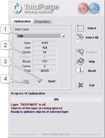 |
Fig. 4
Application's main window
after selecting drawing objects. |
| Note. If during the selection of objects the program identifies layers with the "LOCK", "FROZEN" or "OFF" attributes, it displays the respective message in the message window. Objects located in such layers will not be selected. |
"Optimization" tab controls, Fig. 4:
- (1) "Select Layer" drop-down list
Use this item to manually select the working layer containing objects to be optimized.
Read more in "Selecting layer".
- (2) Information field
Contains quantitative information on entities within selected layer that are to be optimized (including the conversion of objects into polylines).
- (3) "Start!" button launches optimization (and/or conversion of objects into polylines).
- (4) Mode toggle button to switch between manual/automatic layer selection.
Read more on this button in "Selecting layer".
Next, on the "Optimization" tab, select the layer with the objects to be optimzied.
The compilation of drawings created in AutoCAD is based on the principle of layered arrangement. Each object in AutoCAD belongs to a certain layer. Objects in each layer have their unique properties, normally specific to that layer (color, line type, weight, etc.) Therefore, TotalPurge focuses on the layer-based optimization of objects; i.e., only objects of the selected layer are to be processed at a specific moment.
| Terminology: Layer with its name being shown in the title of the "Select Layer" window is called current working layer. |
There are two working layer selection modes TotalPurge can run in:
- Manual layer selection.
- Automatic working layer selection.
The control that toggles the working layer selection mode is the button (4) on Fig. 4.
When the button is pressed (see Fig. 5), TotalPurge switches to the automatic optimization/-conversion of all selected objects in all layers available on the list of the "Select Layer" drop-down list.
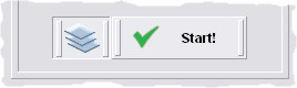 |
Fig. 5
When the button toggling the working layer selection mode is pressed, TotalPurge switches to the automatic optimization/conversion of all selected objects in all layers available on the list of the "Select Layer" control. |
Otherwise, the program runs in the manual layer selection mode.
Manual layer selection mode
In the manual layer selection mode, you can select the working layer to be optimized (and have its objects converted into polylines) using the "Select Layer" drop-down list on the "Optimization" tab, by clicking the button and selecting the required layer from the list.
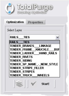 |
Fig. 6
Once the objects have been selected,
select the layer in the "Select Layer" drop-down list. |
Automatic working layer selection mode
In this mode, the "Select Layer" control for the manual selection is disabled and, therefore, all objects on all layers from its list undergo the optimization.
Switching the program to this mode is very useful when it is necessary to optimize all selected objects located on a large number of layers.
| Setting properties to entities |
If necessary, you can set properties to updated optimized objects. This function becomes available to user only with the total optimization mode turned on (see "Program settings ").
Custom settings can be made on the "Properties" tab immediately after selecting objects see Fig. 7.
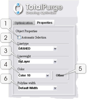 |
Fig. 7
You can modify (set) properties to updated optimized
objects on the "Properties" tab |
Note. All properties set by user on this tab apply only to objects within current working layer, provided that the program is running in the manual layer selection mode (read on selecting current working layer in "Manual layer selection mode").
Please note that once the program is done with objects within current working layer, custom properties no longer apply to objects located within further layers. |
"Properties" tab controls
- (1) "Automatic Selection" checkbox
This check box is set by default when user selects objects to be optimized.
Every time the check box is set, the program automatically recalculates properties of all selected objects, generates property lists, identifies and presets the most frequently used values from the generated lists.
Clearing this check box allows you to modify at your discretion certain properties of updated objects.
| Note. Please also remember that all custom settings of object properties are reset when a new drawing fragment is selected or current working layer is changed. In this case, the check box automatically toggles on. |
- (2) "Linetype" drop-down list
Here you can select and set the line type value to updated objects. The list of line types in this control is formed of objects found within the drawing fragment selected for optimization.
- (3) "Lineweight" drop-down list
Here you can quickly select and set alternative lineweight to updated objects from the standard preset weights.
- (4) "Color" drop-down list
Allows to quickly select and set custom color to updated objects from
preset colors (including ByLayer and ByBlock).
- (5) "Other" button for selecting alternative color
Displays the AutoCAD standard "Select Color" dialog for selecting custom color from AutoCAD Color Index (ACI).
- (6) "Polyline width" drop-down list
Here you can set the width value to polylines created after the conversion of objects into polylines. The list of polyline widths in this control is formed of LWPOLYLINE and 2DPOLYLINE objects found within the drawing fragment selected for the conversion.
If no polylines are found within the selected drawing fragment, only the Default Width parameter is available for selection. In this case, with the "Convert objects into polylines" check box set, the entities will be converted into polylines with the width value set in the Default Width parameter.
The value of the Default Width can be edited in the "Program settings" window on the "Optimization" tab (see "Program settings ").
To launch the optimization of objects within selected layer, click the "Start!" button (see Figure 4).
As the program runs, the message window displays the name of each operation being performed (see Figure 8):
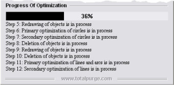 |
Fig. 8
Once optimization is started, the message window
displays information on the progress of the process. |
When you are done, you can exit from the application by clicking the "Exit" button. Once the application is closed, the AutoCAD text window displays a report on the result of the last optimization session.
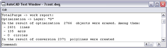 |
Fig. 9
When the application is closed, the AutoCAD
text window
displays a report on the result. |
If you exited from the program while the process was in progress
(i.e. clicked the "Exit" button while the optimization was going on), the report will not be generated and, respectively, will not appear in the text window.
|